Network layout generator module
Overview
A grid network allows different households to connect to the PV Minigrid. Traditionally, in large-scale Integrated Energy Planning, the sizing of distribution networks in settlements is done through indirect calculations based on the number of users, the size of clusters, or by using Minimum Spanning Trees (MST). Alternatively, for single locations the grid is often designed in an manual process.
The rule-of-thumb or MST based approaches are rough approximations that neglect the inherent complexity of the problem. In most cases, when planning, grids follow existing roads, as they can easily bend and branch off to connect more buildings. However, this means the grid does not follow an optimal path but is instead restricted by the topological distribution of households within the settlements. Moreover, road layers might not be available in remote areas where mini-grids are a suitable electrification alternative, leaving a gap in grid sizing that uses roads as an input.
Given this context, OnSSET-MG includes a methodological approach to size the distribution network for a given settlement using its boundaries and the building footprint layer of the households as the main inputs. The module identifies key attributes of the distribution network: trunk lines, branch lines, service drops, and poles. With associated capital costs, it can also compute investment costs and utilize the LCOE equation to estimate distribution costs per kilowatt.
Grid sizing
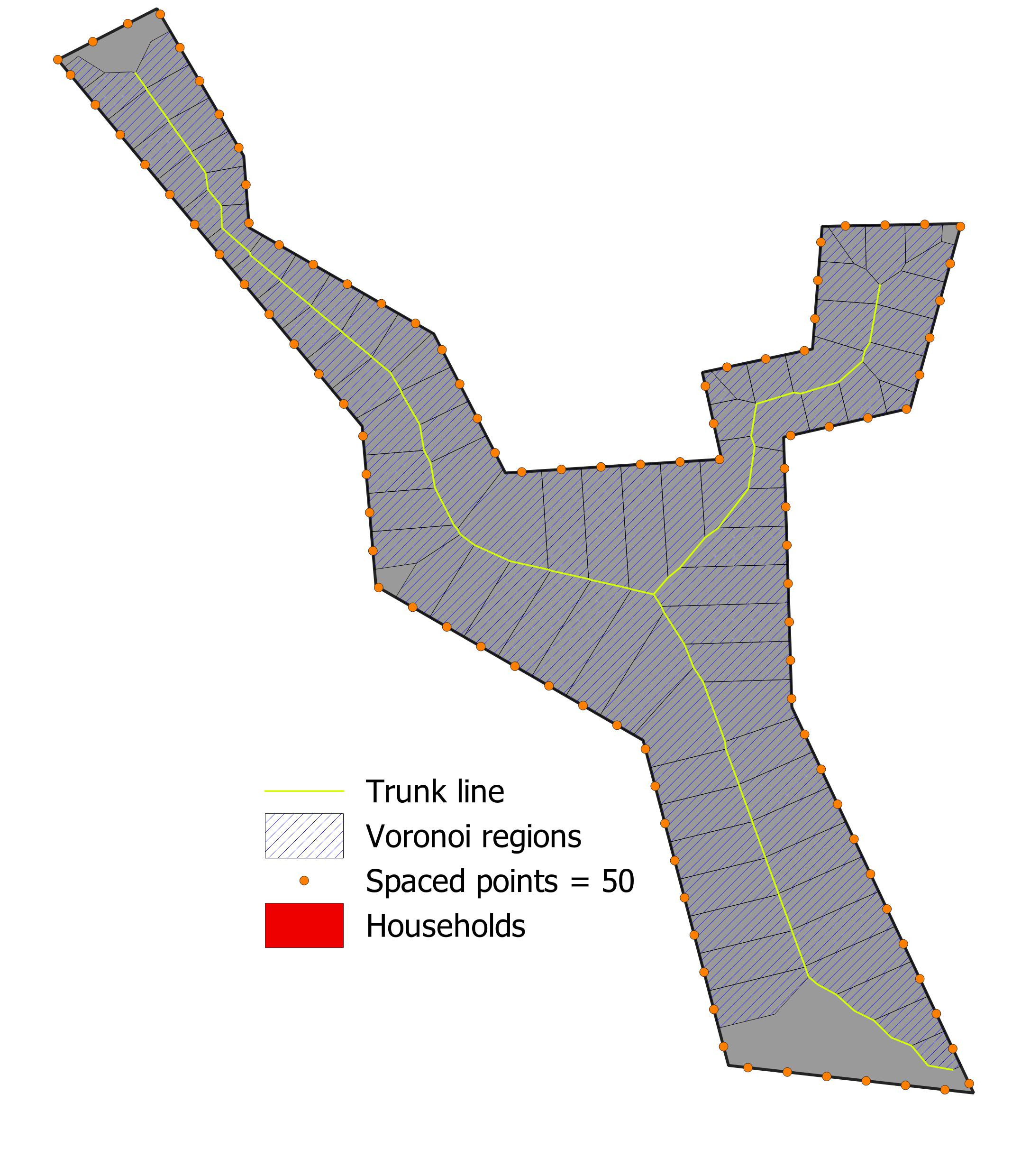
Voronoi polygons are computed using generated points along the cluster boundary at a specified spacing. The edges of the Voronoi polygons are then intersected with the polygon boundaries. Segments that do not intersect are used as a base trunk line. This line is further simplified by removing branches shorter than a specified threshold (see figure below).
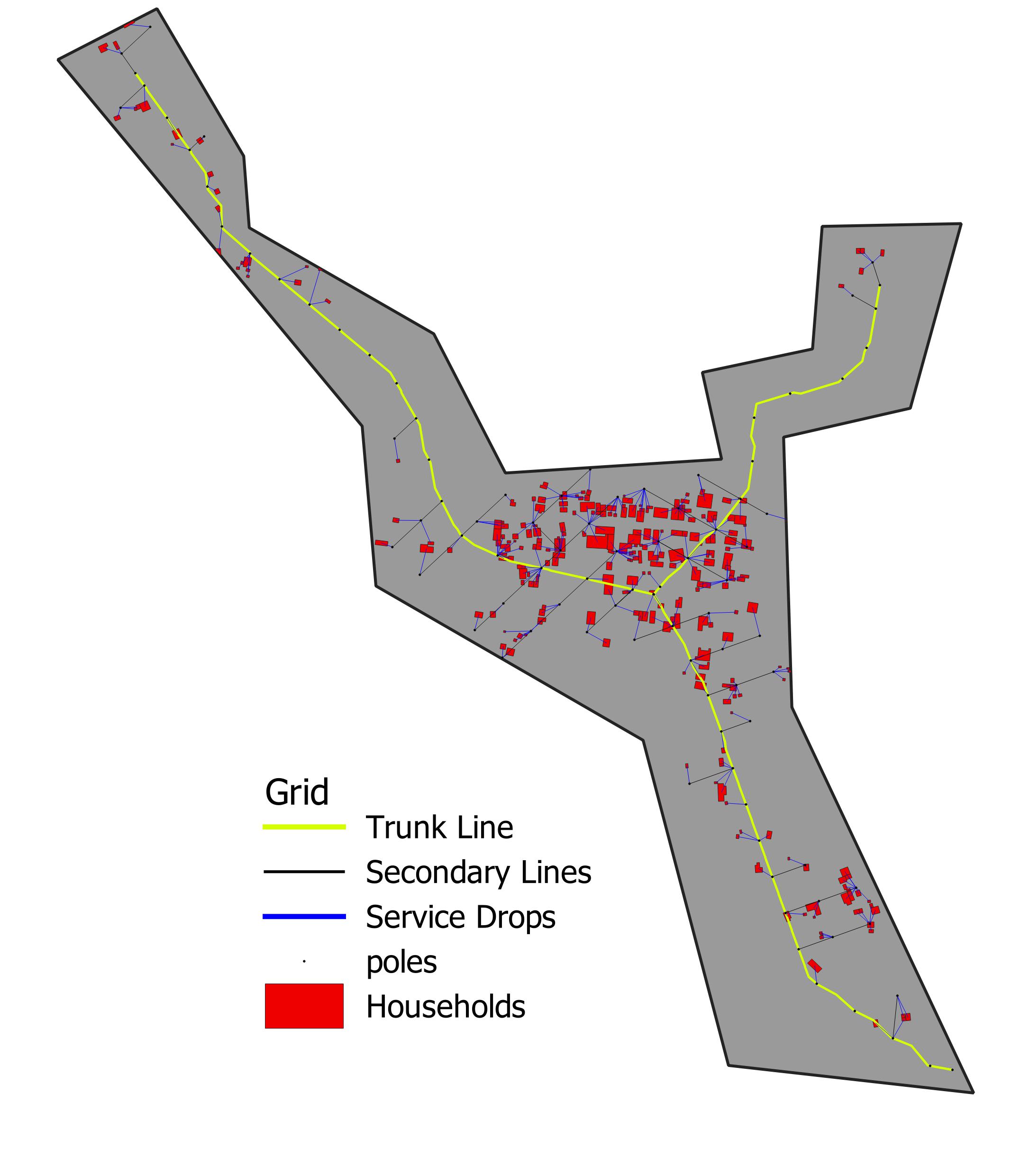
A grid of candidate poles is generated within the Voronoi regions, and households will connect to the closest candidate pole. Then, a weighted MST connects all of the poles to the primary trunk lines. The weights of the MST are assigned to favor the following, in order: connecting two lines on the primary trunk, connecting poles to a nearby pole on the trunk line, connecting two poles aligned along the x- or y-axis of the minimum bounding rectangle to favor orthogonal lines from the trunk, and connecting any other poles. The final result for the same geometry can be observed in the figure below.